I/O Overview
This article is valid only for 52/XD, 52/XC, 52/XS devices.
For related information on 52/RM4200D, 52/XR devices see DSP Frame I/O - Configuring the DSP Frame.
In the I/O Overview section, you can add, remove, and configure all inputs and outputs that belong to your system. You can configure I/O boxes, sub-modules, and device links.
To add an I/O unit to the system, click Add, a list with different I/O units is shown. Select an I/O unit from the list, now it is available in the Select element list.
To delete a selected I/O unit from the list, click Remove.
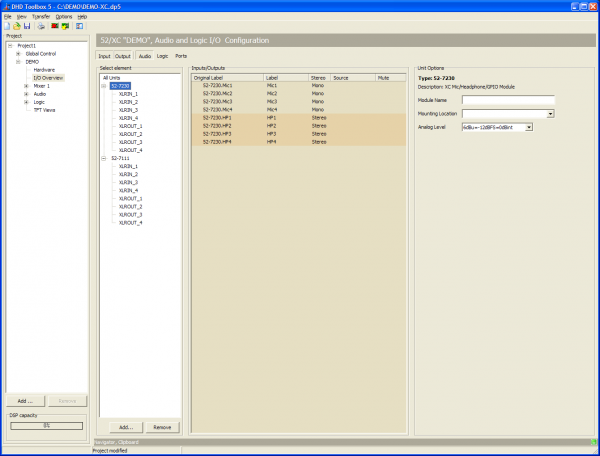
If an I/O unit is selected in the Select elements list, all corresponding audio inputs and outputs are shown in the Inputs/Outputs area.
![]()
Above this list, you can see a set of buttons, which allows you to filter the list for Input, Output, Audio, Logic (GPIO ports), Ports (to show all ports on an I/O module).
To show the required elements, select the corresponding button. To hide elements, deactivate the corresponding button.
Options for each input and output type
The options for each input and output type are described in the following:
Inputs/Outputs area
| Option | Description |
|---|---|
| Original Label | This column shows the internal label which is generated in that scheme: <module type>.<port label> |
| Label | Individual Label, double-click on the label and change the current name. |
| Stereo | Indicates if the signal is mono or stereo. |
| Source | Shows the assigned audio/logic source for input and output. |
| Mute | Shows, that a Mute Logic is assigned to an output. |
IOModule-X.<port> Audio Inputs
| Option | Description |
|---|---|
| Type of Signal | Shows the general signal type of the port. |
| Enter Label | Enter a distinctive name for the selected input. |
| Headroom | Choose the headroom for each input from the corresponding drop-down menu. The shown values always refer to the devices internal default level of 0 dBint. |
| Select M/S | Select, if the signal is mono or stereo. |
| Sample Rate Converter | Select from the drop-down menu, if the sample rate converter is activated (On) or deactivated (Off) for this input. |
| Add to Mixer 1 | Select this check box to create a fader channel in Mixer 1 with that signal as audio source. |
| Fader Start Level | Select a level, which sets the fader start logic to on. |
| Auto Off | By closing the fader, the channel is automatically switched OFF (ON key is deactivated). |
| On Start | The faderstart is only activated and deactivated by pushing the On/Off key, not by moving the fader. |
| Clean Feed | Select this check box to create a corresponding clean feed bus for this signal. |
| Timer Reset | If this check box is selected, opening this fader will reset and start the Auto timer of the stopwatch. |
| Channel On Logic | Select a Logic Function from the Logic Sources window, which sets the channel to ON. You can choose, for example a GPI to open a channel. |
| Channel Off Logic | Select a Logic Function from the Logic Sources window, which sets the channel to OFF. You can choose, for example a GPI to close a channel. |
| Mute Condition Logic | Click Source to select a Logic source, that mutes the input, if the logic source becomes true. |
| Mute Logic 1,2,3,4,5 | Here, you can define which mute logics are enabled when opening a fader. Mostly, this assignment is used to mute speakers when opening microphone channels. You can control up to two mute logics. To do this, select the corresponding check boxes. To assign a mute logic to an output select the mute logic check box at a selected output on this tab. |
IOModule-X.<port> Audio Outputs
| Option | Description |
|---|---|
| Type of Signal | Shows the general signal type of the port. |
| Enter Label | Enter a distinctive name for the selected output. |
| Headroom | Choose the headroom for each output from the corresponding drop-down menu. The shown values always refer to the devices internal default level of 0 dBint. |
| Select M/S | Chose, if the signal is mono or stereo. |
| Sample Rate Converter | Select from the drop-down menu, if the sample rate converter is activated (On) or deactivated (Off) for this output. |
| Dithering | If you connect devices with a lower resolution of the digital signals to a DHD device, here you can define how the internal audio signal is to be dithered before leaving the digital output. With this function, the quality of the output signal can be improved. You can select 16 bit, 20 bit, or Off (no dithering, preset value). |
| Digital Out Mode | This option can adopt the values Pro (default value) or Consumer. See the parameter details below - Digital Outputs - Pro and Consumer values |
Note: Especially for consumer and semiprofessional DAT or MiniDisc devices, you should use the Consumer option, because the might not synchronise properly in which case they display No Lock, for example | |
| Source | You can assign an audio signal to a mono output. Click the Source button, the Audio sources window opens. Select an audio source, and click Assign. |
| Left Source | You can assign an audio signal to the left channel of the selected output. Click the Source button, the Audio sources window opens. Select an audio source, and click Assign. |
| Right Source | You can assign an audio signal to the right channel of the selected output. Click the Source button, the Audio sources window opens. Select an audio source, and click Assign. |
| Direct ACI | Select this check box to enable volume control for the headphones via a potentiometer which is connected to an ACI. This option is only available for headphone outputs. The ACI on D-sub port 1 is assigned to headphone 1 (HP1) and the ACI on D-sub port 2 is assigned to headphone 2 (HP2). |
| Mute Logic 1 | Select this check box to mute this output, if a fader with one of the inputs with selected Mute Logic 1 check box is opened. |
| Mute Logic 2 | Select this check box to mute this output, if a fader with one of the inputs with selected Mute Logic 2 check box is opened. |
| Mute Logic 3 | Select this check box to mute this output, if a fader with one of the inputs with selected Mute Logic 3 check box is opened. |
| Mute Logic 4 | Select this check box to mute this output, if a fader with one of the inputs with selected Mute Logic 4 check box is opened. |
| Mute Logic 5 | Select this check box to mute this output, if a fader with one of the inputs with selected Mute Logic 5 check box is opened. |
Digital Outputs - Pro and Consumer values
On digital Outputs, you can choose between Pro (default value) or Consumer. The following parameters are changed accordingly:
| Mode | Pro (Default) | Consumer |
|---|---|---|
| Terminator | 110 Ohm | 75 Ohm |
| Output voltage | 5 V | 0,5 V |
| Data stream | Professional Bit set | Consumer Bit set |
IOModule-X.<port> General Purpose Inputs (GPI)
| Option | Description |
|---|---|
| Type of Signal | Shows the general signal type of the port. |
| Enter Label | Enter a distinctive name for the selected input. |
IOModule-X.<port> General Purpose Inputs (GPO)
| Option | Description |
|---|---|
| Type of Signal | Shows the general signal type of the port. |
| Enter Label | Enter a distinctive name for the selected input. |
| Select Source | You can assign a logic sources to the selected GPO. Click the Source button, the Logic sources window opens. Select a logic source, and click Assign. |
DeviceLink
To exchange audio signals directly between two 52/XC or 52/XS cores, you can connect them directly by a shielded CAT5 or CAT6 cable on an APC port on each XC/XS core.
To use the DeviceLink, each DSP Core requires an 52-8582 XC/XD/XS Core Audio Network licence.
Each DeviceLink connection can send and receive 48 audio channels at the same time. This connection does not transmit any control signals.